2019-07-24
Latest Project
So, I asked if anyone could figure out my next project...
Corrected schematic:
Sorry that the connectors are not
quite right, couldn't find any Ac wall
plugs or line cords in Kicad...
Here's a PCB layout...
What is it?
Anyone guess?
Board etched and tinned, a
coil off to the side...
(Along with my reading glasses, I hate getting old(er) ;) )
Circuit board complete...
Any ideas yet?
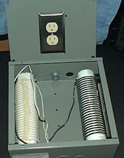
Box with two of the coils mounted...
10 uH each (approximately)
Box is 10" x 10"
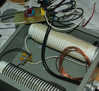
Almost there...
Some pretty thick wire...
Generating a signal into the input
and watching the output on a scope.
Input starting at about 100 Hz
and sweeping to about 100 Khz
Here it is...
What is it?
A Brute-Force Line Filter,
Containing a common mode choke.
Hopefully, to help deal with the
cheap switching wall warts which
pollute the airwaves so much. :/
On to the next project (circuit board with toner layout in the last shot.)
じゃまた
Subscribe to:
Post Comments
(Atom)


0 comments:
Post a Comment